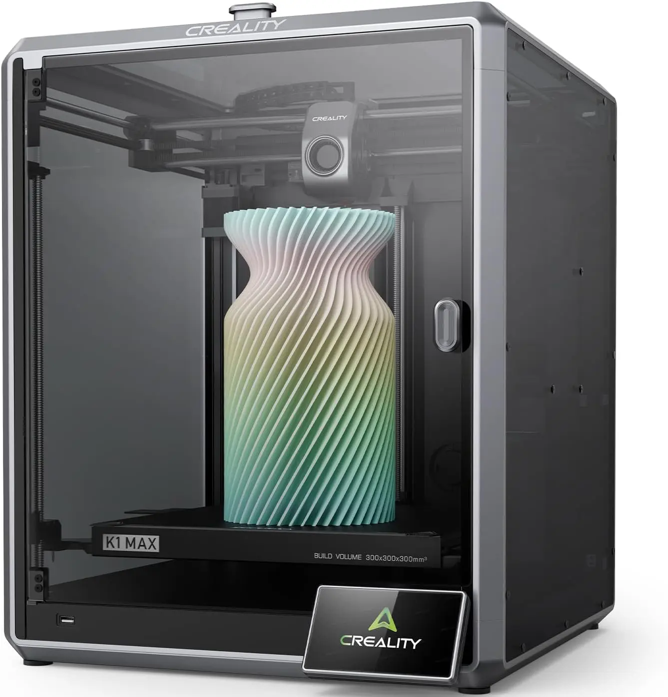
How to Maximize the 600 mm/s Speed on the Creality K1 Max (Without Sacrificing Print Quality)
The Creality K1 Max is advertised with a blazing top speed of 600 mm/s and 20,000 mm/s² acceleration. However, simply cranking the speed slider to 600 mm/s in your slicer usually results in under-extrusion, layer delamination, ringing (ghosting), and rounded corners.
To actually hit high speeds while maintaining retail-grade surface quality, you must solve the underlying physics: volumetric flow limits, cooling capacity, and resonance compensation.
The Core Constraint: The Volumetric Flow Equation
Before changing any settings, remember the golden equation of FDM 3D printing:
$$\text{Volumetric Flow Rate } (\text{mm}^3/\text{s}) = \text{Speed } (\text{mm/s}) \times \text{Layer Height } (\text{mm}) \times \text{Line Width } (\text{mm})$$
- At standard settings (0.20 mm layer height, 0.42 mm line width, and 600 mm/s):
$$\text{Required Flow} = 600 \times 0.20 \times 0.42 = \mathbf{50.4\text{ mm}^3/\text{s}}$$ - The stock K1 Max ceramic hotend safely melts standard PLA at roughly 24–32 mm³/s.
- Attempting 50.4 mm³/s on a stock setup causes immediate extruder clicking, under-extrusion, and brittle sponge-like infill.
To achieve 600 mm/s, you must either:
- Reduce layer volume (e.g., lower layer height to 0.12–0.16 mm), or
- Increase melt capacity (high-flow materials and hotter nozzle temperatures), or
- Target 600 mm/s where it counts (infill and inner perimeters), while preserving outer walls at dedicated quality speeds.
Step 1: Mechanical Tuning & Hardware Prep
High speed magnifies mechanical imperfections. If the frame or gantry flexes, resonance compensation cannot keep up.
- Firm Footing:
- Place the K1 Max on a heavy, solid workbench or a concrete paver with foam underneath. A wobbly desk ruins print quality at 20,000 mm/s² acceleration.
- Clean the Rods Correctly:
- X-Axis (Carbon Fiber / Ceramic): Wipe clean with a dry microfiber cloth and Isopropyl Alcohol (IPA). Never grease the carbon rod—grease traps dust and creates friction.
- Y-Axis & Z-Axis (Steel Rods / Lead Screws): Clean off factory shipping grease and apply a thin film of lightweight synthetic grease (e.g., Super Lube synthetic with Syncolon PTFE).
- Check Belt Tension:
- The CoreXY belts should produce a resonant frequency of approximately 110–130 Hz over a standard span. Uneven belt tension causes oval circles and asymmetric ringing.
- Inspect Extruder Tension:
- Ensure your extruder has the updated blue/metal lever clip (standard on newer K1 Max batches) so tension remains uniform during rapid retractions.
Step 2: Material Selection & Temperature Optimization
Standard filaments take too long to melt and crystallize, limiting flow and layer bonding at short cycle times.
- Use High-Speed Formulations: Switch to Hyper PLA, PLA-CF, or dedicated rapid-melt PETG/ABS with high Melt Flow Index (MFI).
- Bump the Nozzle Temperature by 10°C–20°C:
- For standard PLA usually printed at 205°C–215°C, increase to 225°C–235°C at speeds over 400 mm/s. The plastic spends only milliseconds in the melt zone; higher heat is required for rapid thermal transfer.
- Remove the Top Lid for PLA:
- High-speed printing requires cooling. When printing PLA at high ambient temperatures, open the door or remove the glass lid to avoid heat creep and throat clogs.
[!TIP]
Hardware Upgrade Note: Upgrading to a bi-metal high-flow nozzle (e.g., Creality Unicorn / hardened tip or Trianglelab/Micro Swiss FlowTech) increases flow capacity up to 35–42 mm³/s, opening up higher speeds at standard 0.20 mm layer heights.
Step 3: Calibrate Input Shaping & Pressure Advance
The K1 Max runs Klipper under the hood. You must calibrate resonance and extruder deceleration.
1. Run Input Shaper (Resonance Calibration)
- From the touchscreen or Fluidd/Mainsail interface: Settings > Self Check > Input Shaping.
- Ensure the toolhead G-sensor is mounted securely. Run the calibration with the belts properly tensioned and the enclosure closed to measure structural vibration modes accurately.
2. Calibrate Pressure Advance (PA)
At 600 mm/s, the pressure in the melt zone is extreme. Without precise PA tuning, corners will bulge, and seam starts will starve:
- Use OrcaSlicer’s built-in Pressure Advance Calibration (Line or Tower method).
- Typical K1 Max PA values with direct drive and standard high-speed PLA range between 0.035 s and 0.055 s.
Step 4: Slicer Configuration (OrcaSlicer / Creality Print)
The secret to clean high-speed printing is decoupling outer perimeter speeds from internal speeds and setting a Volumetric Speed Ceiling.
1. Set the Maximum Volumetric Speed (The Safety Cap)
Under Filament Settings > Max Volumetric Speed:
- Stock Hotend + Hyper PLA: Set to 28–30 mm³/s.
- Stock Hotend + Standard PLA: Set to 20–24 mm³/s.
- Why this matters: The slicer automatically slows down only on geometries where the flow exceeds your hotend’s physical limit, preventing extruder jams while permitting 600 mm/s whenever cross-sections allow.
2. Optimize Speed Hierarchy
| Feature | Target Speed | Rationale |
|---|---|---|
| Outer Wall (Perimeter) | 200 – 300 mm/s | Gives consistent surface gloss, sharp features, and no ghosting. |
| Inner Wall | 450 – 500 mm/s | Provides structural backup; hidden from view. |
| Infill | 550 – 600 mm/s | Fully internal; maximizes time savings. |
| Solid / Top Surface | 150 – 200 mm/s | Ensures watertight, smooth top layers without pinholes. |
| Travel Speed | 600 – 700 mm/s | Rapid non-print moves. |
| Initial Layer | 50 – 70 mm/s | Guarantees bed adhesion. |
3. Acceleration & Jerk Settings
- Set Normal Acceleration to 12,000–15,000 mm/s² (scale up to 20,000 mm/s² only for infill and travel).
- Keep Outer Wall Acceleration at 5,000–8,000 mm/s² to preserve surface definition.
4. Infill Pattern Selection
- Never use Grid or Triangles: At 600 mm/s, nozzle crossings will clip previous lines, causing loud nozzle strikes, layer shifts, or ripped infill.
- Use Gyroid or Cross-Hatch: These patterns do not cross paths on the same layer, allowing effortless 600 mm/s moves.
Step 5: Thermal Management & Fan Tuning
At high speed, layers print in seconds. If the layer isn’t cold before the next one is laid down, parts warp and overhangs curl upward.
- Auxiliary Side Fan:
- Enable the large 18W chamber side cooling fan at 70%–90% for PLA.
- Directs high-velocity air across the entire build plate to freeze overhangs immediately.
- Minimum Layer Time:
- In Cooling settings, set Minimum Layer Time to 3–4 seconds.
- On tiny points (like the chimney of a 3DBenchy), the slicer will deliberately slow down or pause to allow plastic solidification.
Step 6: Step-by-Step Calibration Sequence
Follow this workflow to dial in your machine safely:
flowchart TD
    A[Mechanical Check: Belt Tension & Clean Rods] --> B[Run Self-Test & Input Shaping Calibration]
    B --> C[Max Flow Rate Test: Find True Volumetric Ceiling]
    C --> D[Pressure Advance Calibration for Sharp Corners]
    D --> E[Configure Slicer: Max Volumetric Speed + Gyroid Infill]
    E --> F[Test Print: Speed Benchy / Calibration Cube]
    F --> G{Defects Detected?}
    G -- Ringing / Ghosts --> H[Lower Outer Wall Accel to 5,000 mm/s²]
    G -- Corner Bulging --> I[Tune Pressure Advance]
    G -- Matte / Weak Infill --> J[Increase Nozzle Temp by 5-10°C or Lower Max Flow Cap]
    G -- Perfect --> K[Production Ready at 600 mm/s]
Verification Checklist
- Belts calibrated to ~120 Hz and carbon rod dry/cleaned with IPA.
- Filament Max Volumetric Speed capped at ~28 mm³/s.
- Nozzle temperature bumped +15°C above standard profile.
- Gyroid or Cross-Hatch infill selected.
- Outer wall speed kept under 300 mm/s with outer acceleration at 6,000 mm/s².
- Auxiliary side fan enabled for PLA.